 Potato Robotics
- 24 mins Project Goal
The ultimate goal for this course is to build a fully autonomous aluminum can collector that will be able to compete in the 253/480 Robot Competition. There are some key features that the robot must be able to perform:
- Line following
- Can detection
- Can collection
- Basic self-localization
- Return to starting position
The robot also needs to be constructed entirely from scratch, from prototyping, mechanical design, electrical design, to software programming.
Brainstorming Ideas
Our team had multiple brainstorming sessions where we sketched some preliminary designs according to the required features above.
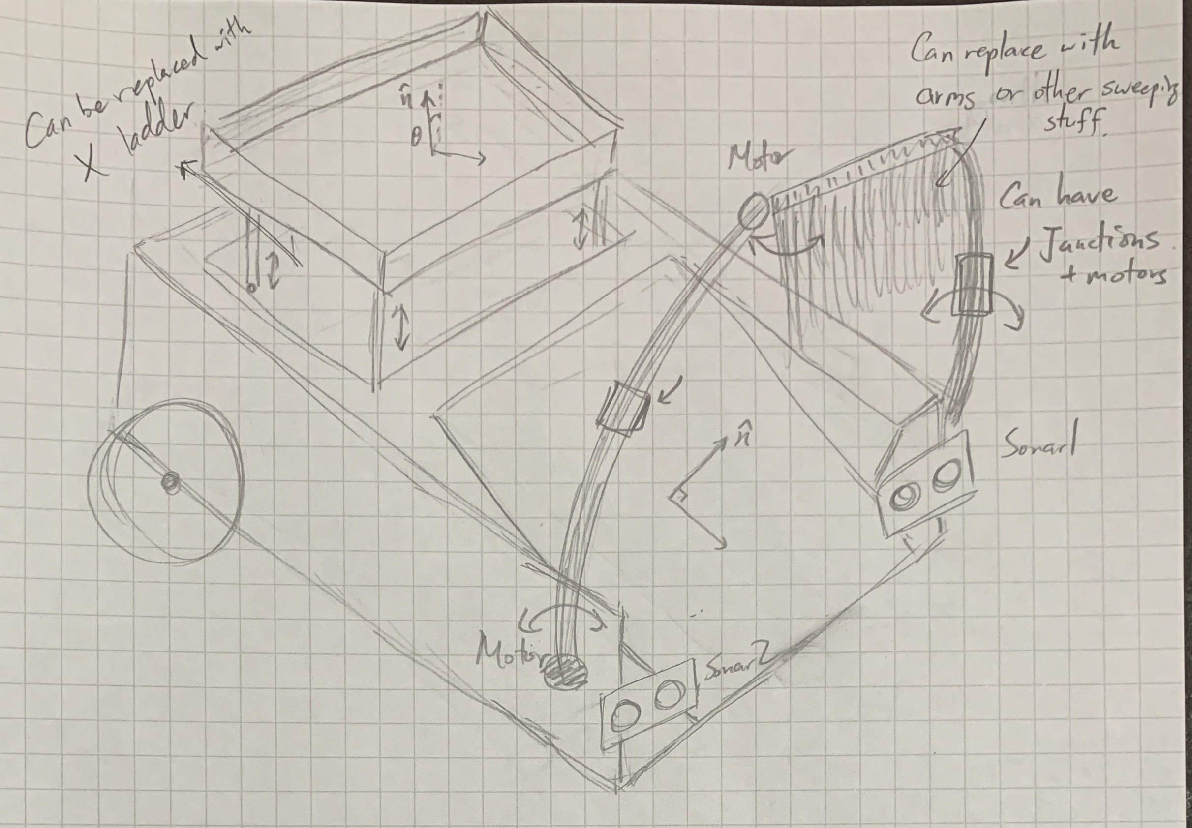
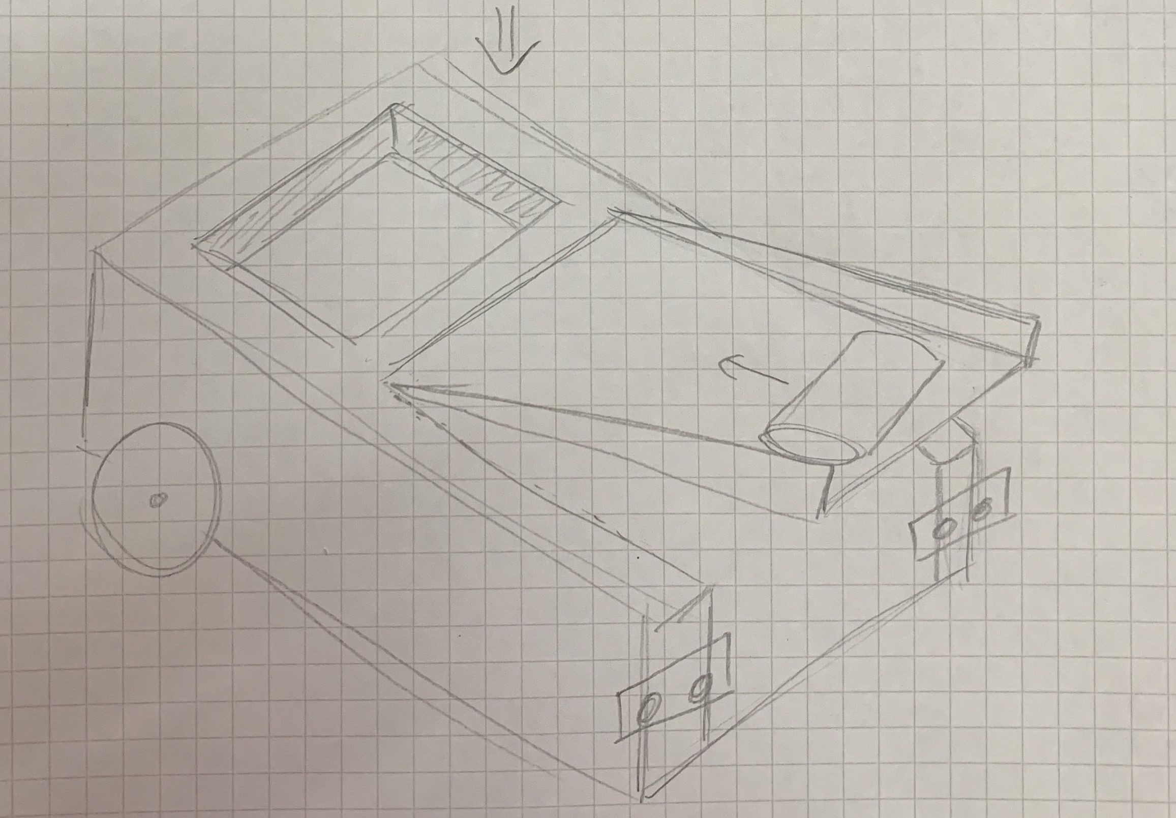
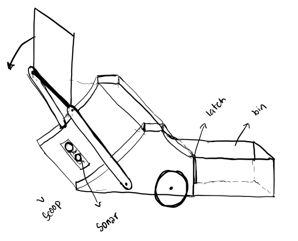
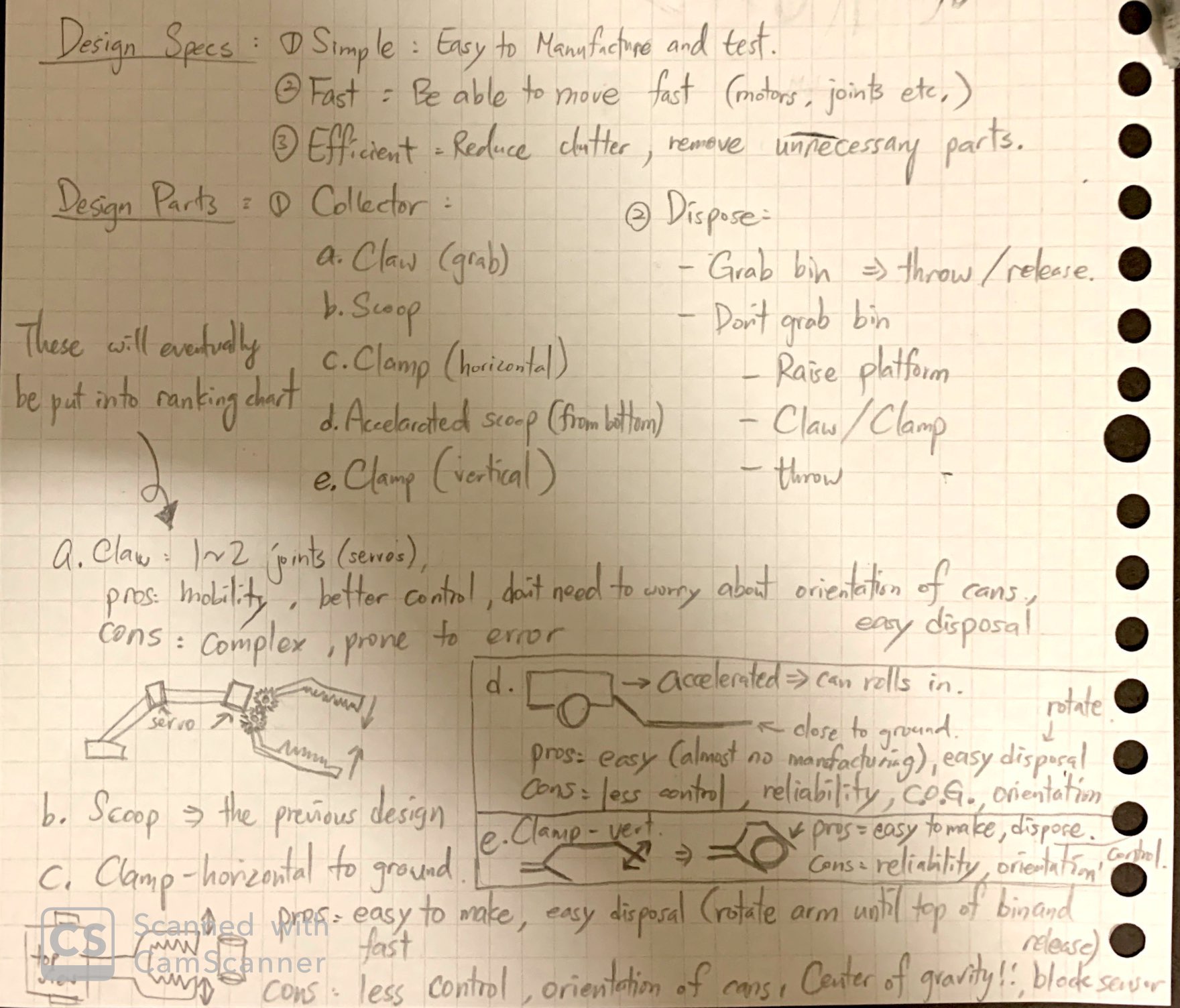
After several group discussions, we decided to go with the claw + dragging-the-bin design.
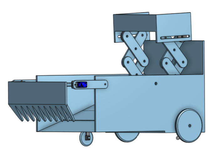
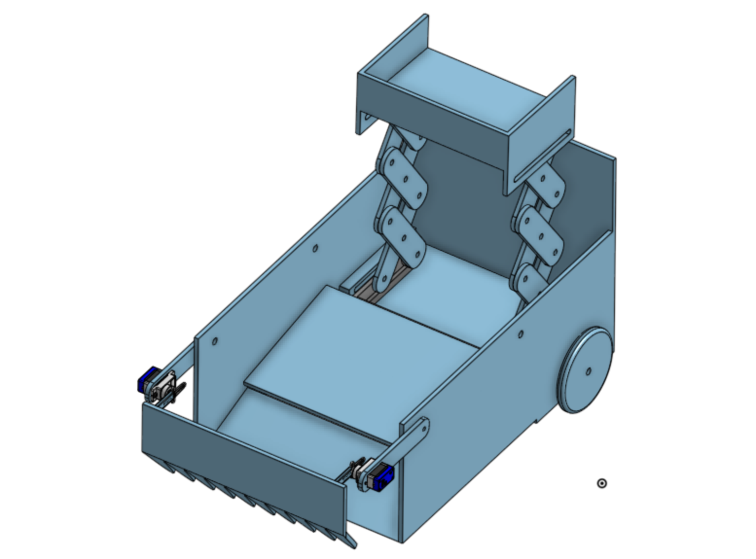
Mechanical Design
We used onShape for our CAD prototyping and simple materials like cardboard, pop sticks and straws for physical prototyping. The robot can be divided into three parts:
Chassis Design
The main design criteria are as followed:
- weighted approppriately: so that the tires can generate enough friction without consuming too much power
- firm: able to tow the bin and operate without deforming
- compacted: has the appropriate length and width to centralize the center of mass, and able to contain all electrical and mechanical components
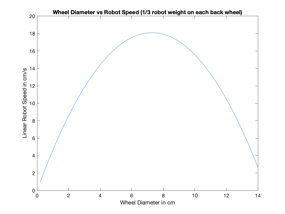
Wheel Design
The radius of the wheels is determined by the weight of the robot, the roughness of the tires, and the total energy loss when the robot is moving (wheels, motors, dissipated heat, weight distribution, etc.). To obtain a practical wheel radius, I wrote a MATLAB script that plots the optimal wheel radius. (source: this research)
motor_torque = rolling_force.*wheel_radius;
speed_rpm = -slope.*motor_torque + max_speed;
speed_linear = speed_rpm.*rpm_to_rpsec.*wheel_circumference;

plot(2.*wheel_radius/cm_to_m, speed_linear/cm_to_m);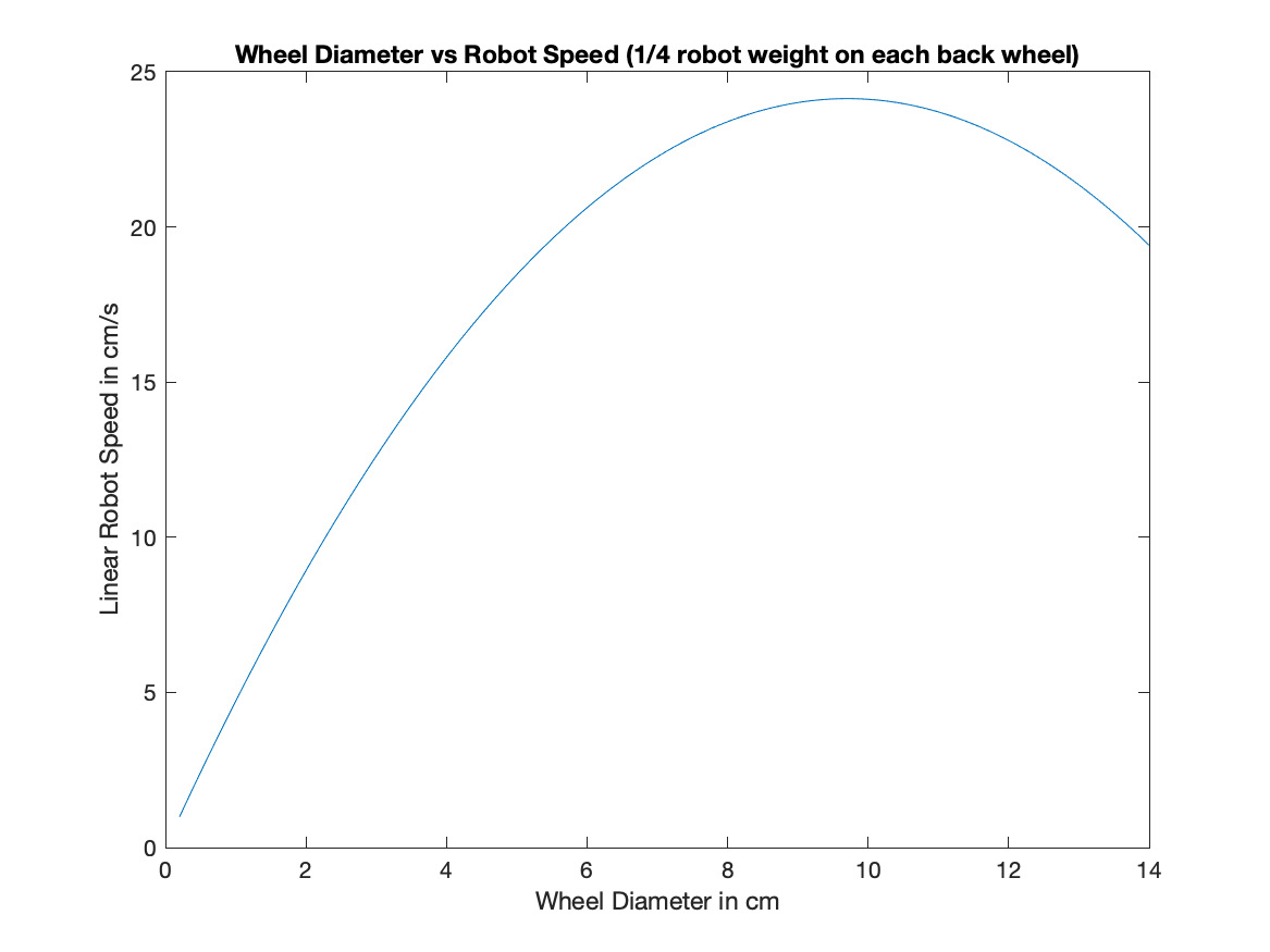
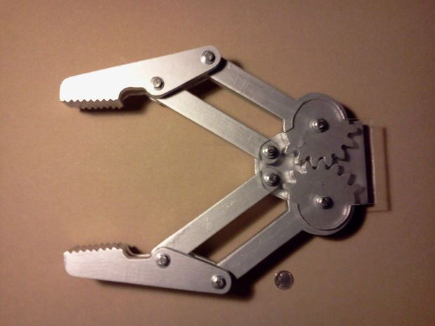
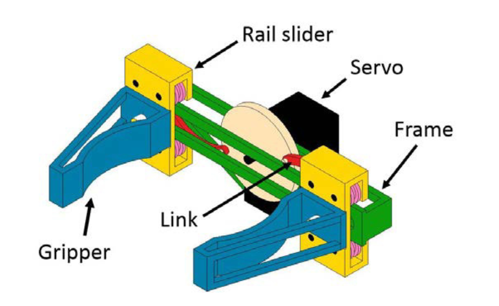
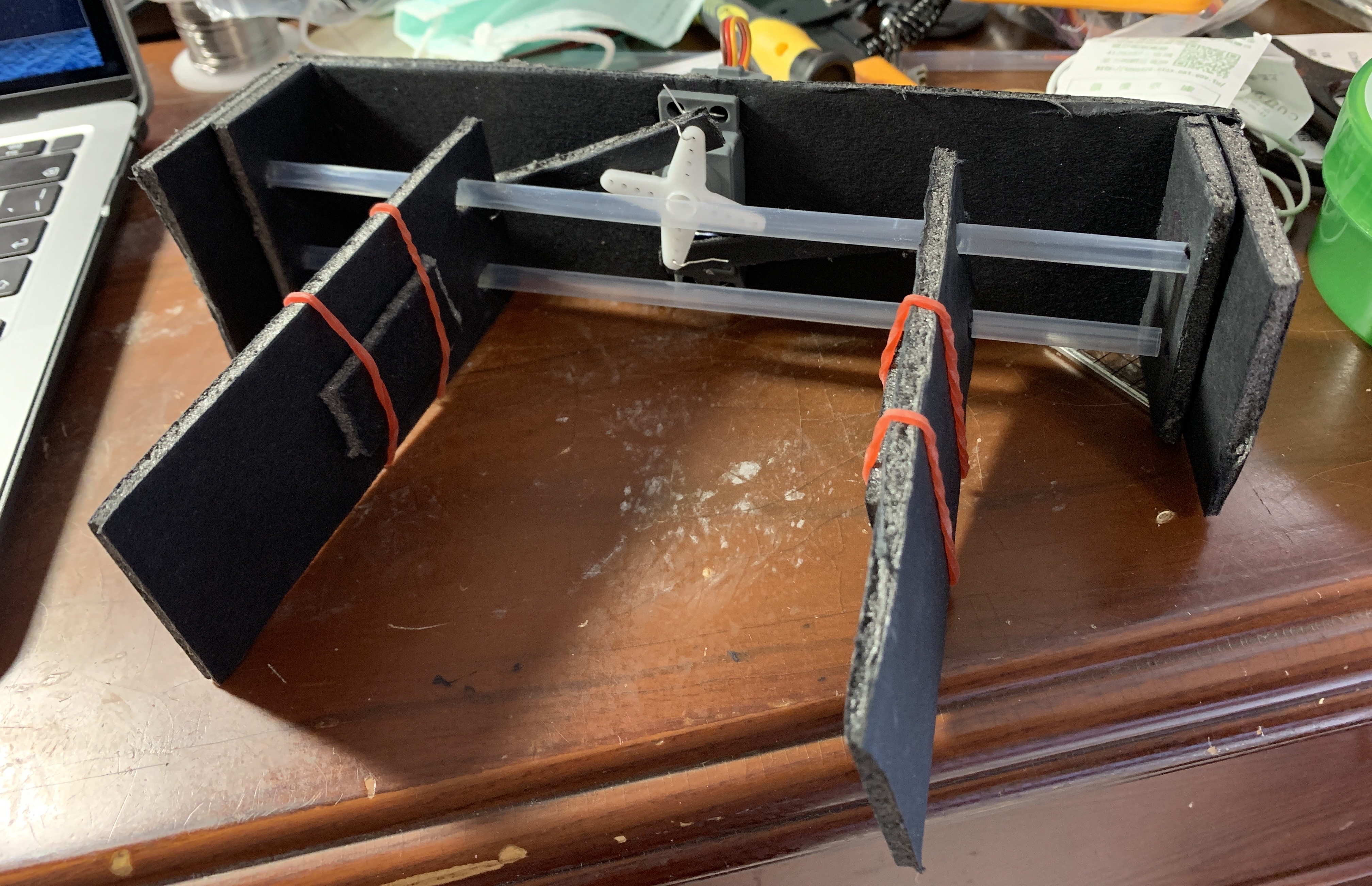
Claw Design
These are the initial claw ideas we had. However, due to the material limitation, we couldn’t make gears that is firm enough and able to smoothly operate.
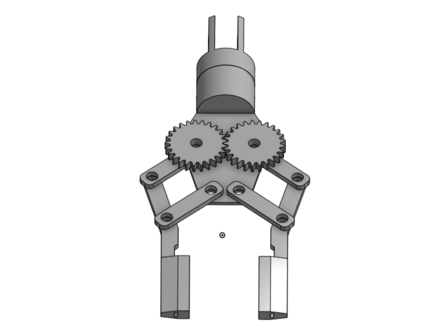
After some research, I finalized a claw design that is similar to the geared claw desgin, but is achievable with a strong enough structure and a double rail for the claws to slide on.
Electrical Design
In this project we have to design our own circuit for controlling the robot as well and the components are limited to basic electrical components (resistor, diodes, capacitors, AND/OR/NOT gates, etc.). The steering of the robot is completely controlled by the angular velocity differences between the wheels and the angular velocity of the wheels is controlled by the current flowing through it. We are not allowed to use pre-programmed or unauthorized motors or chips that facilitates this mechanism.
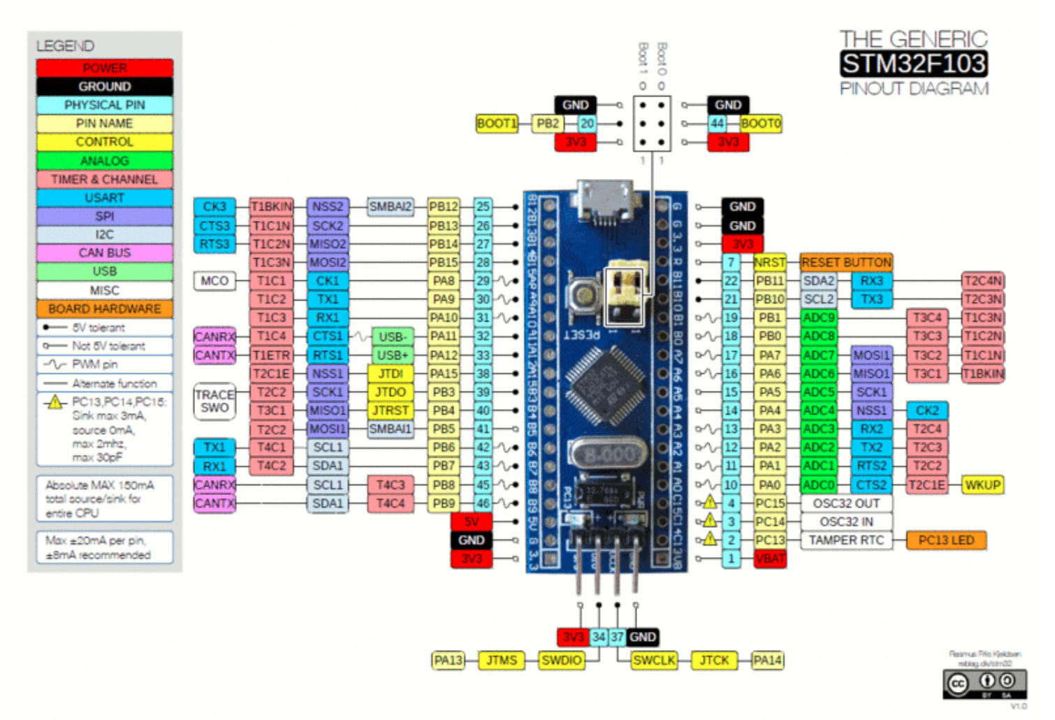
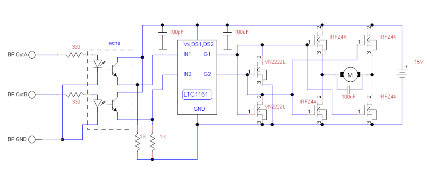
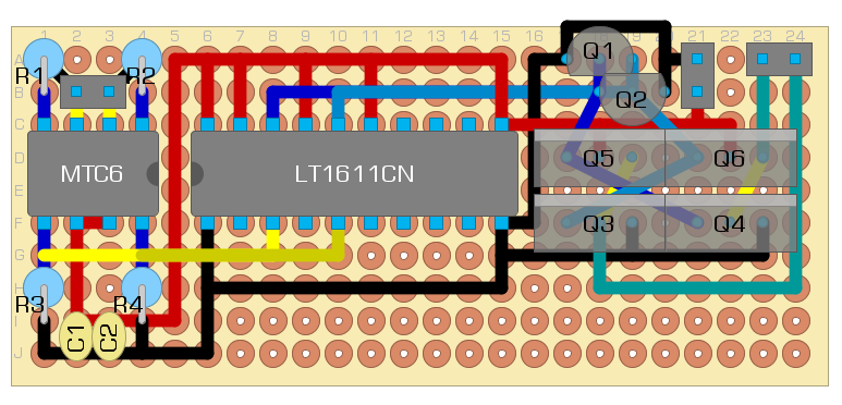
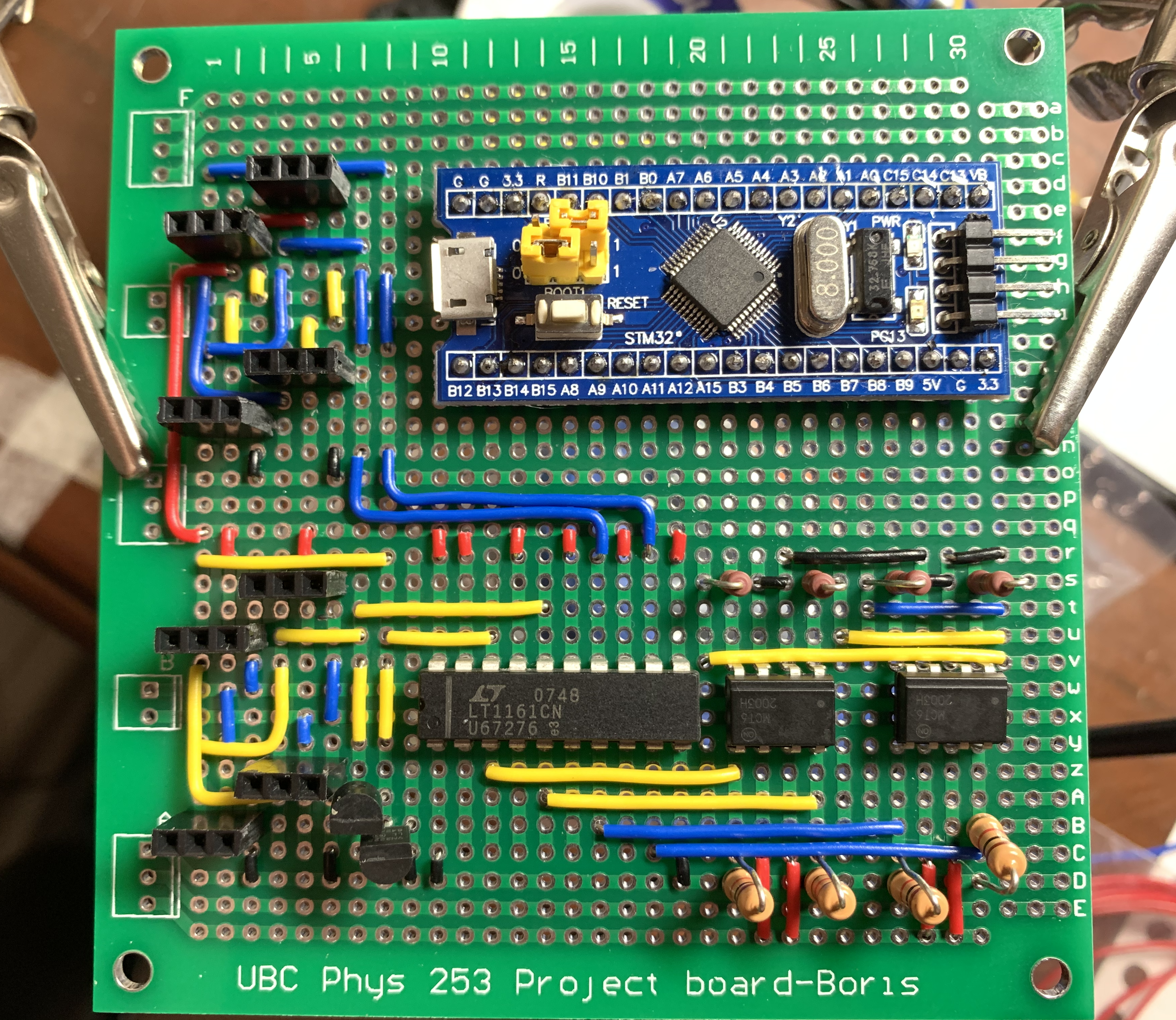
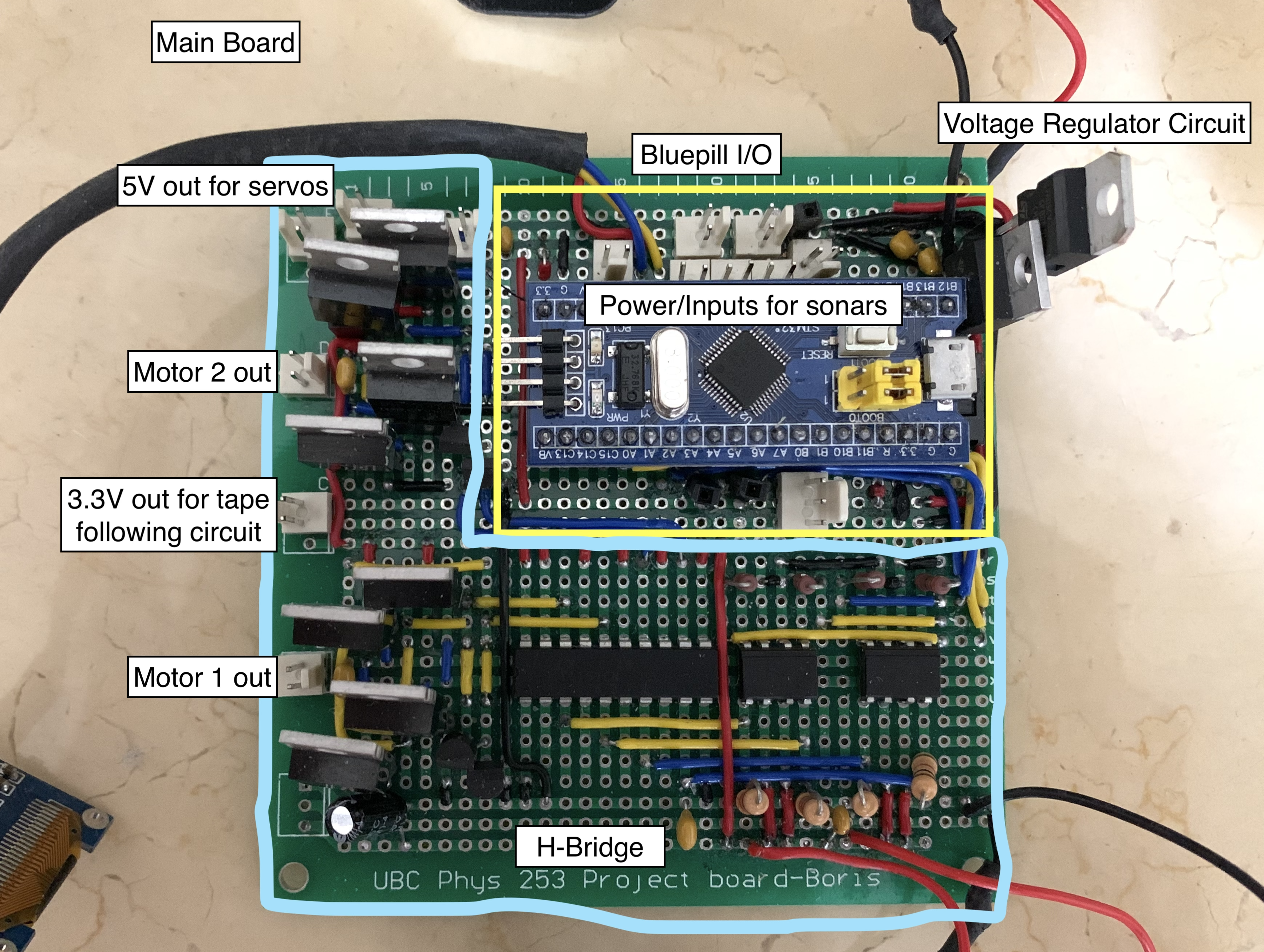
We are using the STM-32 Blue Pill Microcontroller Board for the main controller of this project. To control 4 motors at the same time by regulating the amount of current through the motors, we use a H-Bridge circuit to achieve that. Normally, the H-Bridge circuit can be bought as a integrated chip, but in order to have a deeper understanding of circuit design, soldering and circuit debugging, we build our own.
The two main electrical components in this project are H-Bridge, IR detector and Control.
H-Bridge Circuit
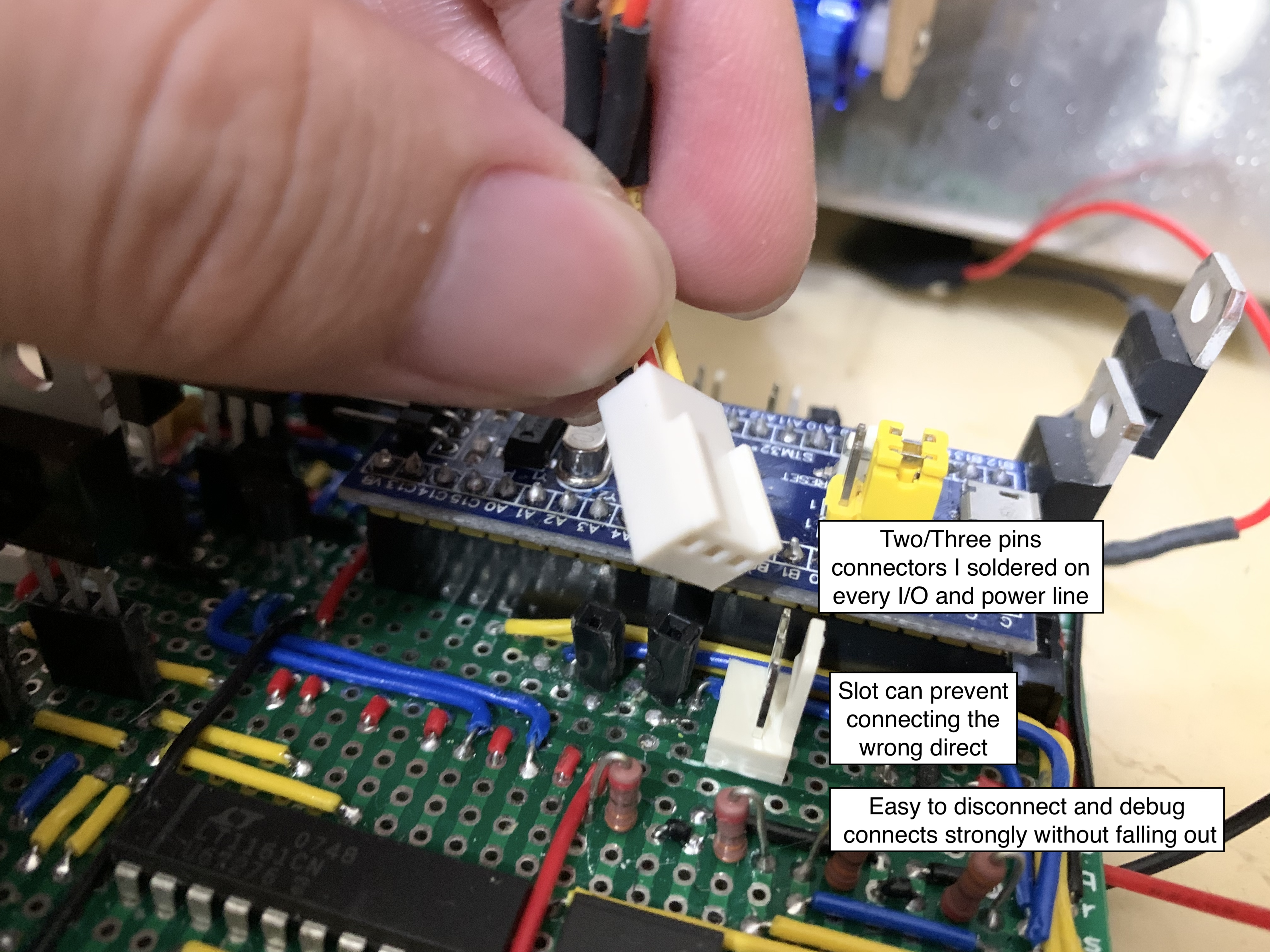
Side Note: I also found this little power clip really useful ![]() (reduces cluttering) :)
(reduces cluttering) :)
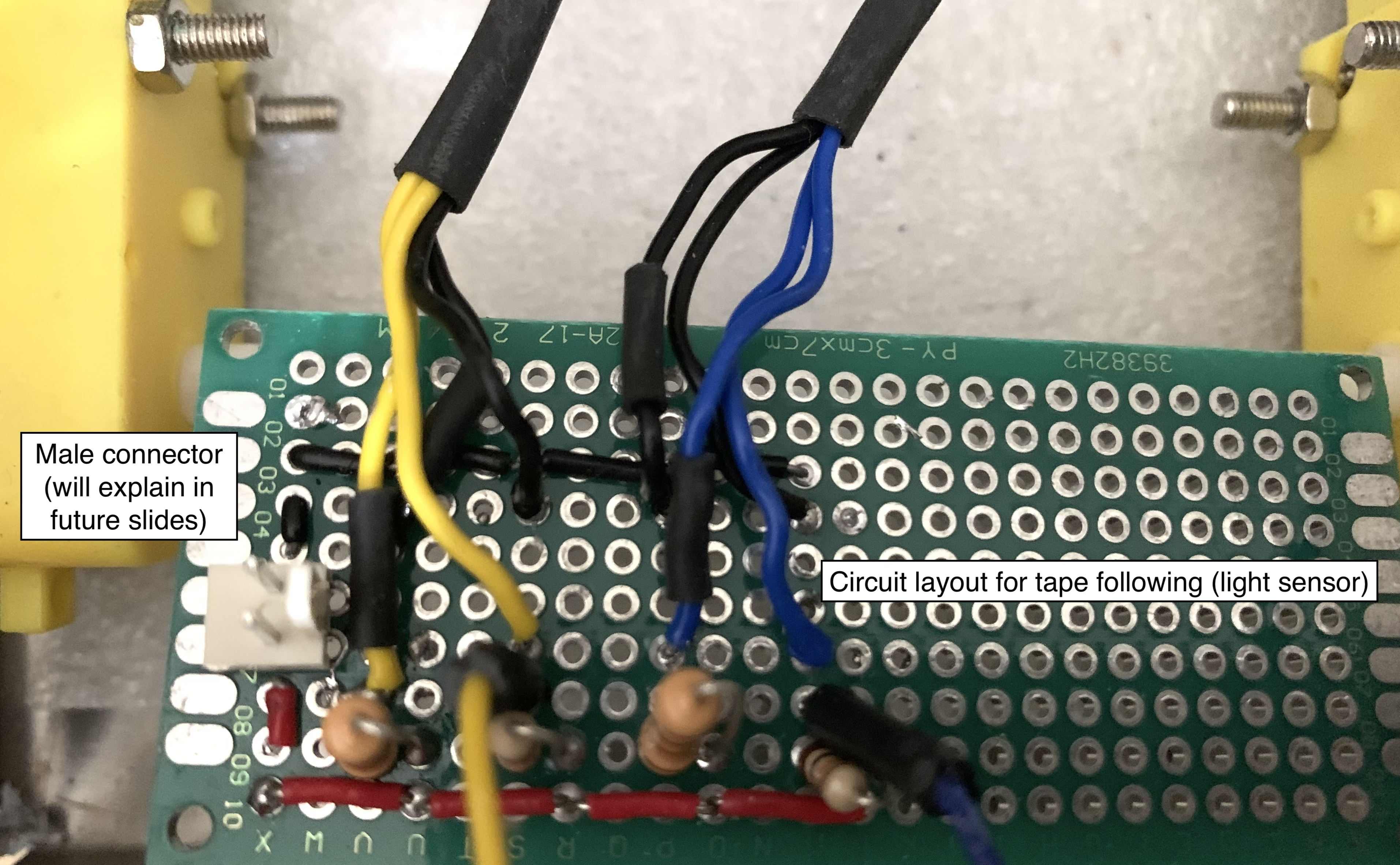
IR Detection (Tape Following)
The robot also has to be able to maneuver itself around the competition arena, and the best way for it to do so is adding the tape following feature. The only approved way to guide this robot is via black tapes (no remote control allowed for it to be completely autonomous). We have two phototransistors (TCRT5000 Reflective Optical Sensor with Transistor Output) in front of the robot that detects the black tape on the ground. It will signal the robot to stay on the black line as it moves.
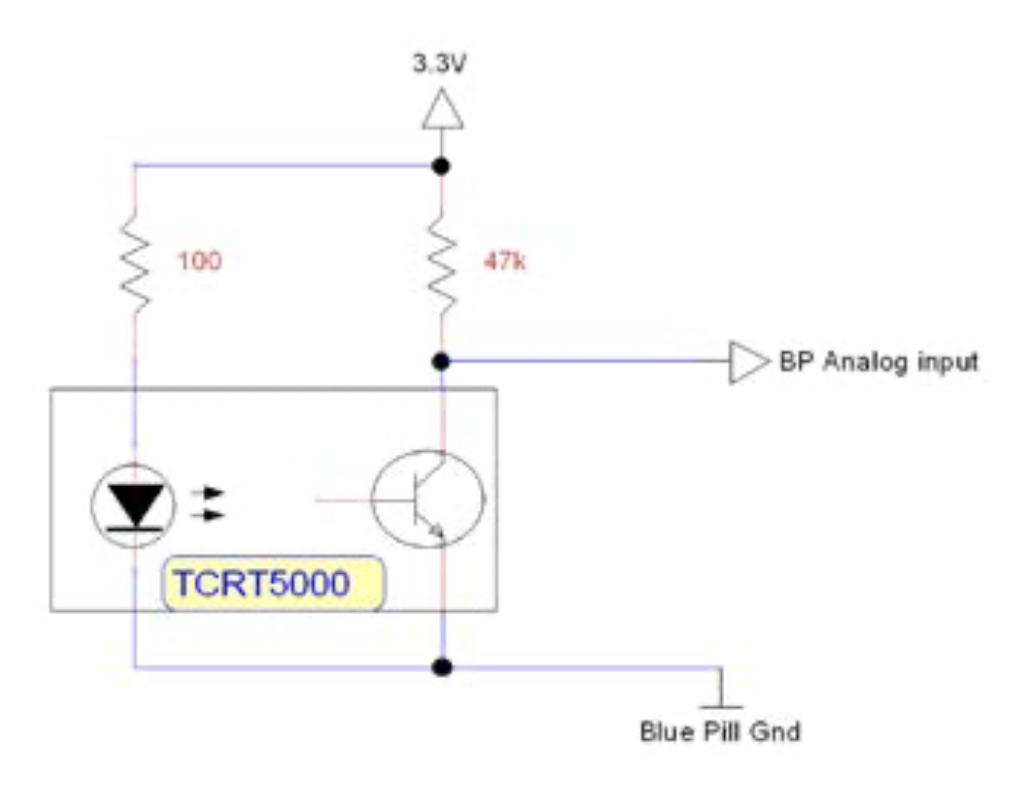
Controlling the robot using two light sensors can actually be challenging, that is why we need PID control to navigate the robot smoothly.
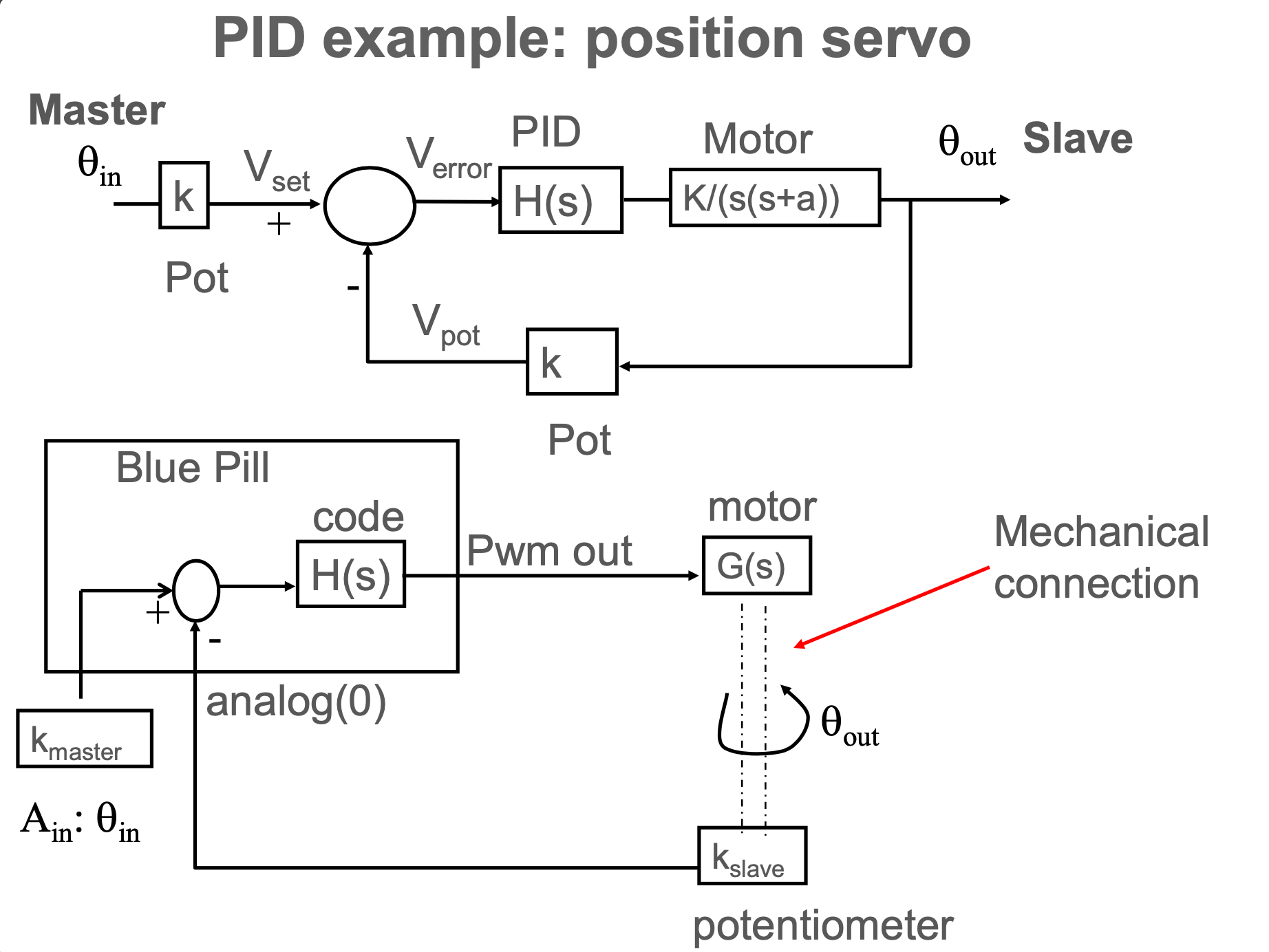
PID Control
PID is a crucial concept in control systems which stands for Proportional, Integral, and Derivative. If we just map the values captured by the phototransistors linearly to the rotational speed of the wheels, the robot will move in a very unstable fashion (jiggling side to side a lot). We want the robot to able to not only generate a smooth, stable trajectory, but also knows how to react when the black tape directs it to a sharp turn. We introduce feedback loops that consist of fine-tuned gains (proportional, integral, derivative) to control the final output of the wheel speed.
| Situation | Left Sensor | Right Sensor | Robot Offset from Tape | Response |
|---|---|---|---|---|
| Both Sensor on Tape | 1 | 1 | 0 cm | Straight |
| Left On, Right Off | 1 | 0 | 1 cm | Slight Left |
| Left Off, Right On | 0 | 1 | -1 cm | Slight Right |
| Both Sensor Off (Left was last on) | 0 | 0 | >= 5 cm | Left |
| Both Sensor Off (Right was last on) | 0 | 0 | <= -5 cm | Right |
Now that we have the electrical portion set up, we need software programming to actually analyze the light sensor outputs and perform the PID control.
Software Construction
Our software is written in primarily C++. I divided the robot into three main classes (DriveSystem, SonarSystem and ClawSystem) and added subclasses as needed.
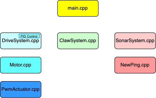
Drive System Code
DriveSystem controls the motors, i.e. speed control, steering, brake, etc. It has a child class Motor, which mainly commands the wheels to spin forward or backwards. There is another class under Motor, PwmActuator, which performs lower level communications with the bluepill board, such as reading and writing to a specific pin. The wheel speed can be directly regulated by the analog value written to that specific pin and the h-bridge is designed to draw power to supply the motors according to that analog value. For example, rotating can be commanded by setting one side 0 and another side ROTATE_SPEED.
void DriveSystem::rotate_left() {
    this->update(0, ROTATE_SPEED);
}

void DriveSystem::rotate_right() {
    this->update(ROTATE_SPEED, 0);
}Sonar System Code
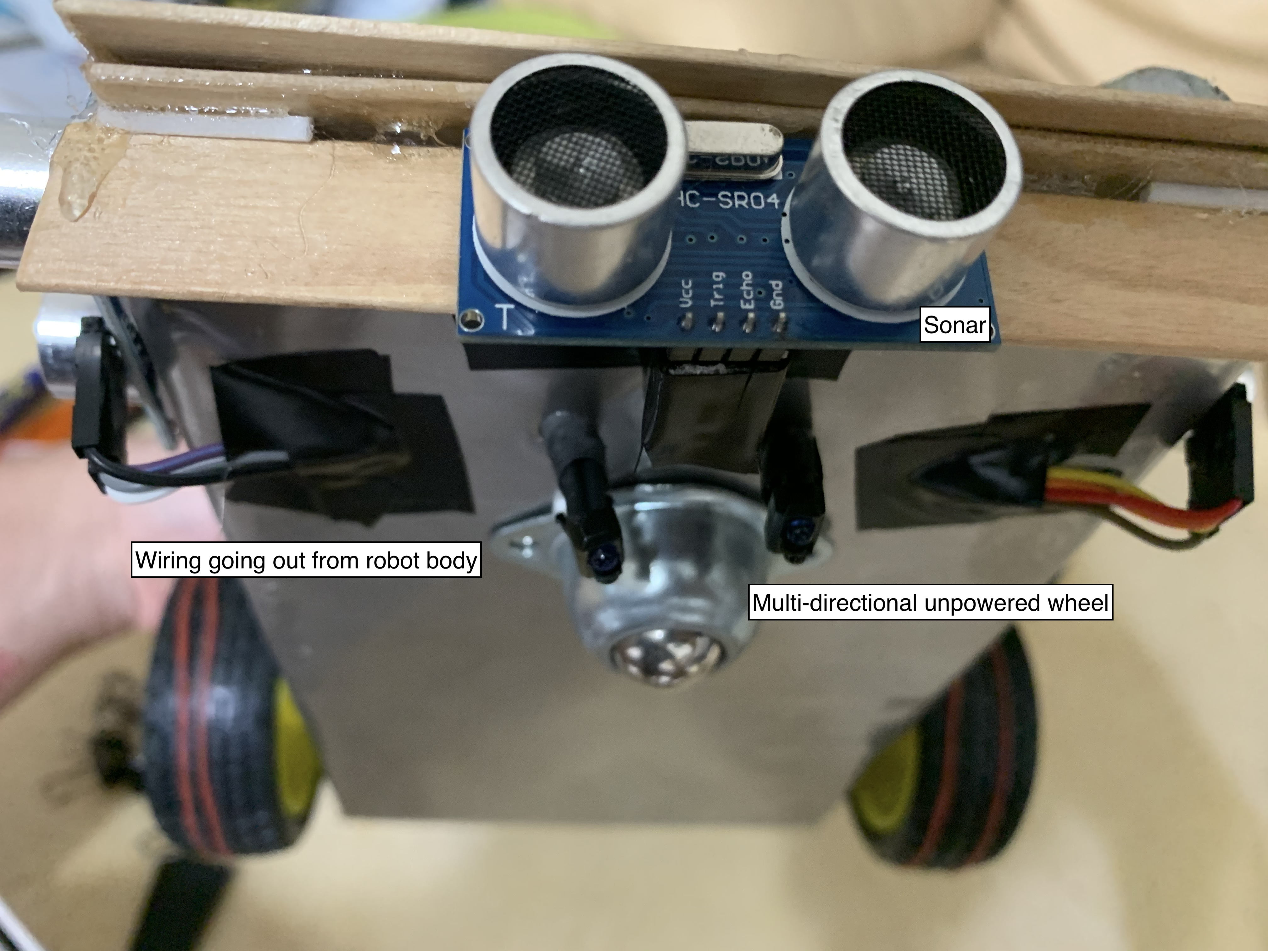
There are three sonars that detects cans: front, left, right. If any one of the sonars detects an obect closer than around half a meter (50 cm), it would initiate a process that collects the cans.
SonarSystem::SonarSystem(int left_trigger, int left_echo, int front_trigger, int front_echo, int right_trigger, int right_echo) {
    SonarSystem::sonar_left = new NewPing(left_trigger, left_echo, MAX_DISTANCE);
    SonarSystem::sonar_front = new NewPing(front_trigger, front_echo, MAX_DISTANCE);
    SonarSystem::sonar_right = new NewPing(right_trigger, right_echo, MAX_DISTANCE);
}Claw System Code
Claw system is initiated when the robot starts and will be activated whenever the sonar system detects a can that is close enough to the robot. It controls a motor that lifts and drops the claw, and another motor that open and closes the claw.
void ClawSystem::open_claw() {
    this->claw_servo.attach(this->claw_pin);
    delay(200);
    for (int servoPos = 90; servoPos >= 59; servoPos--) {
        this->claw_servo.write(servoPos);
        delay(33);
    }
    for (int servoPos2 = 59; servoPos2 <= 90; servoPos2++) {
        this->claw_servo.write(servoPos2);
        delay(32);
    }
    this->currentPos = "open";
    this->claw_servo.detach();
}

void ClawSystem::grab_can_sequence() {
    this->open_claw();
    this->lower_arm();
    this->grab();
    delay(100);
}Final Results and Thoughts
Eventually, all of our robots are able to successfully follow the tape and collect cans! I had multiple 10/10 runs before the competition and was really proud of what I have achieved and the skills that I have learnt. We got into top 8 in the final competition and was tied at the fifth place. Despite of making our individual robots during the pandemic, I am still extremely satisfied with the results and our accomplishments.
Making robots is really fun! ![]()